Facilities > Laboratories > Experimental Modelling
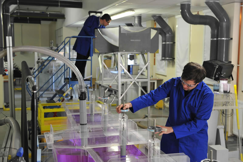
The Experimental Modelling Laboratory supports clients by simulating the process flows. Typically, computational fluid dynamics (CFD) or experimental modelling methodologies are applied.
- CFD modelling utilises Ansys Fluent software.
- Experimental modelling involves the design and running of bespoke models to simulate process flows. These models are scaled down from the plant process in terms of geometric and dynamic scaling (the forces involved).
Within the experimental modelling laboratory is a dedicated laser safety area which is where the laser based velocity measurements are taken. The technique used for velocity measurements is Particle Imaging Velocimetry.
Where appropriate to the model, and customer requirements, the experimental models are automated (via in-house expertise) with data logging from the instrumentation.
Application of these bespoke models includes:
- Slag rabbling within the desulphurisation process
A model with in-built flexibility, allowing the ladle to be altered to match different plant designs in terms of blade design, skim speed, ladle lip design, ladle tilting angle and slag viscosity.
- Slag dart modelling via a process methodology
A model to assess process variables, slag dart density, taphole geometry, slag dart geometry, steel retained and slag carried over, providing information to plant on what to expect when changes are made.
- Slag dart modelling via a fundamental methodology
A model to assess the design of the slag dart via a fundamental methodology. The model variables include: taping rate, slag dart design (head and stem), taphole geometry (including wear), converter tapping angle, effect of steel and slag levels.
- Ladle teeming
A model looking at ladle teeming to investigate slag carryover whilst reducing steel retention.
- Ladle bubbling
A model looking at the effect on the bulk flow patterns from ladle bubbling.
- Ingot teeming
A model looking at the teeming process of an ingot, investigating velocities, flow patterns and mould powder entrainment.
- Slab caster submerged entry nozzle modelling
A fully automated and data logged model looking at the submerged entry nozzle or shroud design within the continuous caster (billet through to slab). Variables include: section size, casting speed, immersion depth, gas injection rates and locations, SEN/SES design and stopper tip design.
- Tundish flows
A model allowing visualisation of the flow within the tundish to help optimise flow patterns and floatation using turbostop, impact pads, dams, weirs, bubbling blocks plus design changes.
- Upper nozzle gas injection model
This model investigates where the gas is injected into the upper nozzle and stopper flows, with the important pressure drop below the stopper included. This innovative model is a step forwarded from a standard tank bubbling test.

